I teach machine design at Yale (MENG 325) and one of the challenges I’ve worked to address is finding a hands-on project that meets a few different goals at the same time
- Mirrors the content covered in homework and lecture
- Teaches students to machine parts and master specific operations
- Guides students through design decisions, good design principles, and a complete design
- Teaches the importance of tolerances and GD&T and provides documented examples of it
- Develops an intuition for material selection
In the past, I had students design their own crushers starting with a provided kinematic diagram for the 6-bar crusher. However, to better support the teaching objectives above, I designed a rock crusher.
Design and Analysis
My design process began with identifying systems that would require several types of analysis: power train, gear stress and fatigue, shaft stress and fatigue, bearing stress and fatigue, kinematics, and mechanics of materials. I also preferred to avoid mechatronic systems to simplify the project. Eventually, I found rock crushers.
A double-toggle rock crusher is a 6-bar mechanism that is commonly used in industrial crushing machines for extremely strong, hard materials, such as granite. The machine derives its strength from its unique 6-bar mechanism which is comprised of a modified Pitmann mechanism for high compression forces and a crank-rocker 4-bar mechanism for driving the Pitmann mechanism. The double-jointed knuckle at the heart of the mechanism gives two sharp impact events in short succession.
I began with a kinematic position, velocity, and acceleration analysis for the 6-bar mechanism, using dimensions derived from schematics of actual rock crushers. I programmed the analysis and animation in MATLAB.
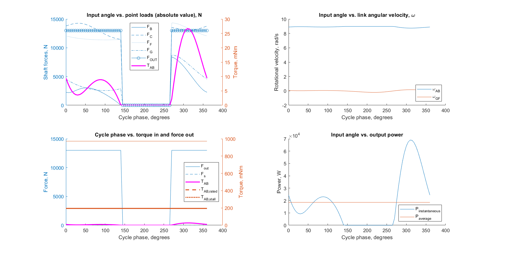
(Top left) It’s easy to see the double-toggle action in the predicted force curve, shown in the top left. (Top right) the rotational speed of the input shaft is quite high compared to the speed of the moving jaw, which bounces around 0, corresponding with an extremely high mechanical advantage. (Bottom left) the torque requirements change over time, but still fall within the motor operational specs. (Bottom right) the predicted instantaneous power curve also shows the double toggle action, and the average power (neglecting losses) matches the expected value.
Once I had the kinematic analysis completed, I then moved to the force analysis of the components. The force analysis is traced backwards through the system. When the jaw is crushing, the force is determined by the deflection and compressive strength of granite. When the jaw is retracting, the force is defined as zero. Any other forces are due to springs, friction, etc. The force is back calculated to the motor.
I then used motor analysis to forward calculate the speed everywhere in the system, based on the linear brushed DC motor model.
While I have written shaft, bearing, and gear solvers, they are not yet integrated into a single software suite.
Manufacturing
The entire rock crusher was made from off-the-shelf components or custom parts made on a wide variety of machines. Each part was designed with a specific manufacturing skill in mind.
- Gears — off the shelf, but modified by drilling and tapping the hub
- Shafts and pins — lathe grooving, parting
- Chassis plates — mill zeroing, positioning, and drilling, and one CNC operation for a larger hole
- Fixed jaw — order of operations on a mill
- Moving jaw — mill facing, reaming, order of operations
- Strike plates (protective covers for the jaws) — cutting, drilling, and tapping steel
- Flywheel — facing steel on a lathe
- 6-bar links — 3D printing
- 6-bar exterior braces — water-jet cutting and reaming
The assembly steps were also designed to teach various standard design techniques. The flywheel uses a shaft key whereas the gears use set screws. All shafts uses appropriate spacers and lock rings. All fully-rotating shafts used ball bearings and all partially rotating shafts used bronze plain bearings.
Materials were selected based on the load type. Parts in pure compression were allowed to be any material, such as 3D printed PLA. Parts in bending or tension were made from aluminum to provide sufficient rigidity and to simplify manufacturing. Parts subjected to surface wear or crushing were made from steel, except the flywheel which was made from steel due to its density.
The tolerances were also designed to be either as loose as possible or at standard machining tolerances to illustrate where tight tolerances were needed or not.
The power supply, motor, and motor controller were supplied. Students soldered their own leads.
Engineering documentation
The engineering documentation was drafted according to ISO standards and with AISI B4 fit standards where needed. Below is one example of the chassis plates.
Results
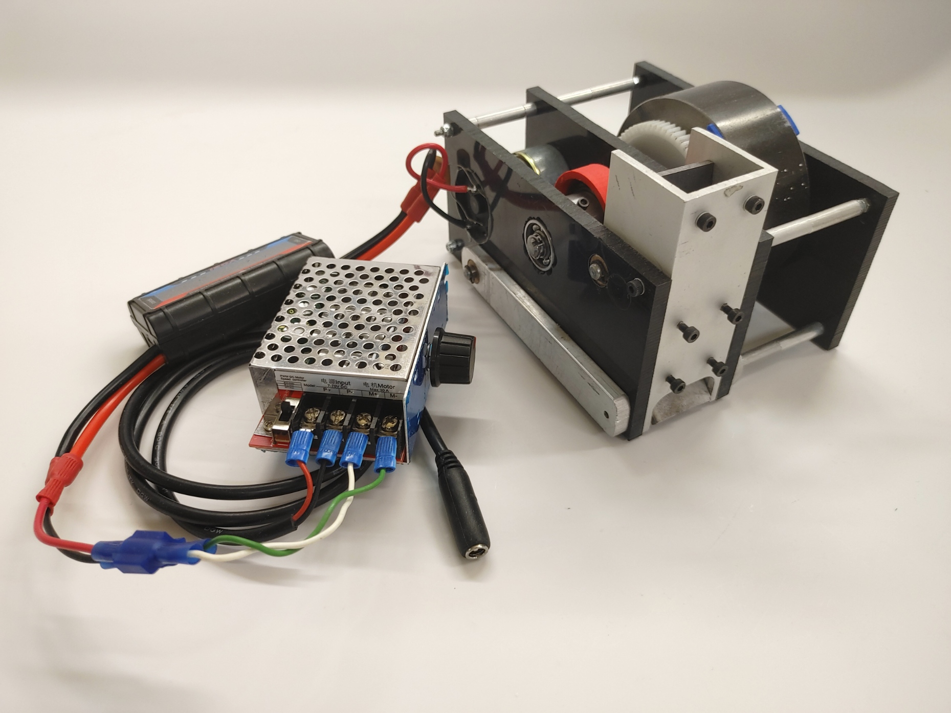
Surprisingly, the rock crusher only requires a 6W power supply. I use this fact to illustrate to the students the power of mechanical advantage and system power analysis. Theoretically, the rock crusher should be able to operate on less, but there are too many places the structure can deflect, requiring at least a few Watts to over come the deflection. However, these elements are left as they are to illustrate this fact as well.
Above is the demo rock crusher that I manufactured. It took me about 12 hours, but most of that time was spent experimenting with different techniques and finding highly repeatable procedures to minimize student frustration.
The students were required to design, manufacture, and install covers that met OSHA safety standards, particularly around the moving parts. Specifically, no finger was allowed to come in contact with any moving part.
In a future update, I will post examples of student work.
