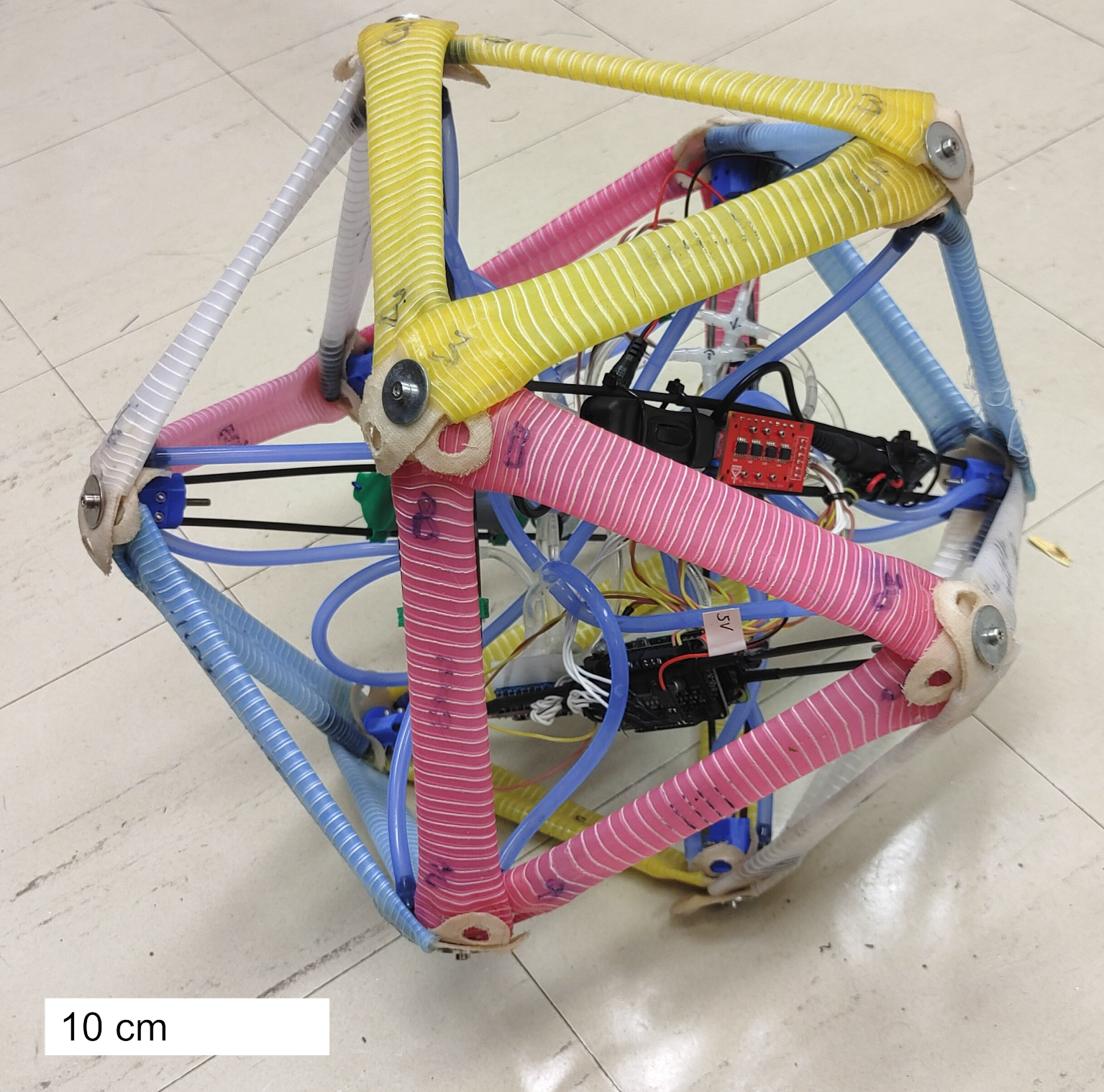
The assembled hydraulic tensegrity
This unique robot attempted to create the first untethered fluidic tensegrity by using a number of novel approaches to reduce power consumption and mass while maintaining significant control authority.
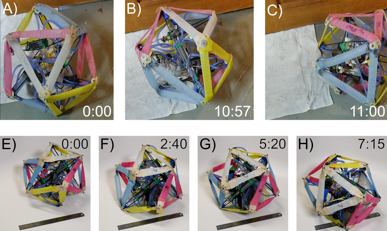
The key insight to this robot design was the accidental discovery during prior work that locomotion could be achieved by expanding a single equilateral triangular face of a 6-bar tensegrity.
This insight led to the design and construction of a purpose-built robot that unlike all prior fluidic tensegrities, also incorporated its battery, pump, and control valves onboard. It also allows for a three-fold reduction in the number of control components since the rotational symmetry of the design can be reduced from 24 active edges to 8 active faces.
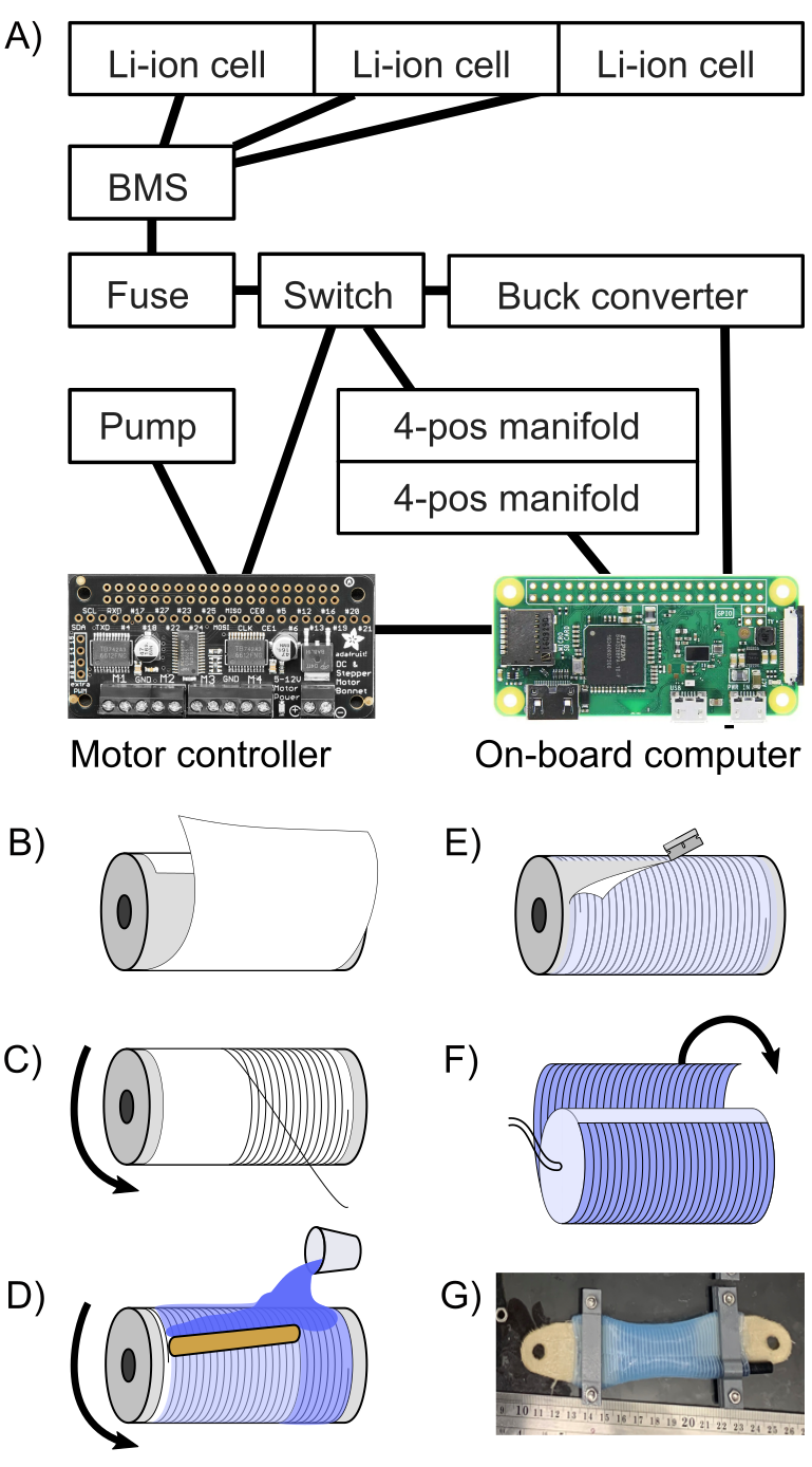
A) The electronics system on the robot. This robot is not proprioceptive and lacks sensors, and is open-loop controlled.
B through G) The manufacturing steps for the fluidic actuators. These actuators use embedded strain limiters which cause the majority of deformation to occur axially.
One design challenge for this robot is that the actuators expand axially rather than contract, making them prone to buckling. To combat this, all of the actuators are designed significantly shorter than their rest length, causing all to be in tension at rest. Consequently, when an actuator is expanded, it is designed to never leave a tension regime. This strategy is similar to how tensioning rods are used in concrete bridges to prevent the concrete from ever undergoing tension.

The fluidic control for this robot takes a novel approach. Instead of using a standard reservoir and accumulator in the fluidic circuit, these functions are embedded in the actuators themselves. The control valves then become a fluidic equivalent of an electronic H-bridge: allowing fluid to flow from one set of actuators (the reservoir) to another (the activated actuators). This strategy allows the electronics to be reduced even further, providing even greater mass savings.

The rod design for the tensegrity also features two parallel carbon fiber rods to allow for the system components to be placed between them. This allows for the mass to be axially centered in the rods, an important consideration for tensegrity designs since the rods come in close proximity.
The battery for the tensegrity consists of six 18650 Li-ion cells, distributed evenly across three of the rods. This arrangement allowed for the mass of each rod to be calibrated so that each rod had a mass of 100g.
The rod assemblies were tested in compression to validate whether they would be a failure point if the robot were to fall, with the results shown above. Further, buckling is not a failure mode in this robotic system, meaning that in an axial impact, a single rod can support a 250N impact load and still survive. However, a lateral load may be more damaging. However, the rods are much stronger than the actuators, which fail at much lower tensile loads.
Lessons Learned and Future Work
The final robot was capable of limited locomotion, but as with other fluidic tensegrities, the strain limit of the actuators still prevented the system from having full locomotion capability. Additionally, the chosen pump was extremely slow, causing locomotion to be unsatisfactorially glacial.
In future work, a few things can be attempted. The first is to reduce the cross-sectional area of the actuators, which consequently can reduce the total volume of liquid that must be displaced, and therefore reducing time.
The mass of the robot was also too high, and a simple fix is to not use 18650 Li-ion cells and use a smaller form factor instead. Another limiting factor was the use of a slow pump, so a future iteration may use a lower pressure but higher flow-rate pump.

Leave a comment